Test Operation Guide
Model: GRM-310K
Version 0.8
Author: James GAO
Table of Contents
For Internal Use Only
Test Operation Guide
0. Terminology
DUT: Device Under Test
VSWR: Voltage Standing Wave Ratio
For Internal Use Only
Test Operation Guide
1. Purpose
This document introduces the test operation for UHF reader module GRM-310K. With this test setup, it is possible to evaluate the DC power consumption, transmit frequency, transmit power, read range and read count performance.
For Internal Use Only
Test Operation Guide
2. Test Conditions
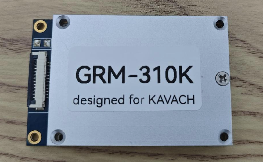
2-1. DUT
A GRM-320K module (Figure 1) without any external accessory.
GRM-310K
designed for KAVACH
2-2. Test Equipment and Setup
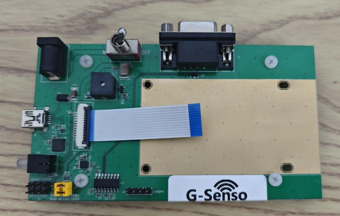
- DC Power
The DUT requires a +5 VDC power input. It is recommended to first connect the DUT to a G-Senso development kit motherboard (Figure 2) with an FPC cable, then power the motherboard from the DC jack connector with a DC adaptor or a voltage supply.
DUT may be permanently damaged at +5.5 V or above.
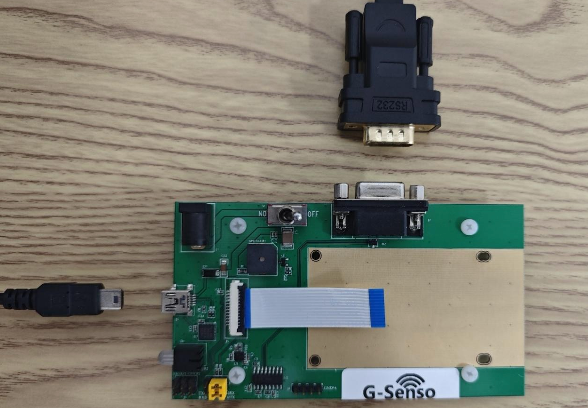
- Serial Port Connection
A stable serial port connection between the DUT and PC is required. The connection must support 912.6 kbps baud rate. With the G-Senso development kit motherboard, there are two on-board serial ports:
- Virtual USB serial port on a mini-USB connector
- RS-232 port on a DB9 connector (Figure 3)
For Internal Use Only
Test Operation Guide
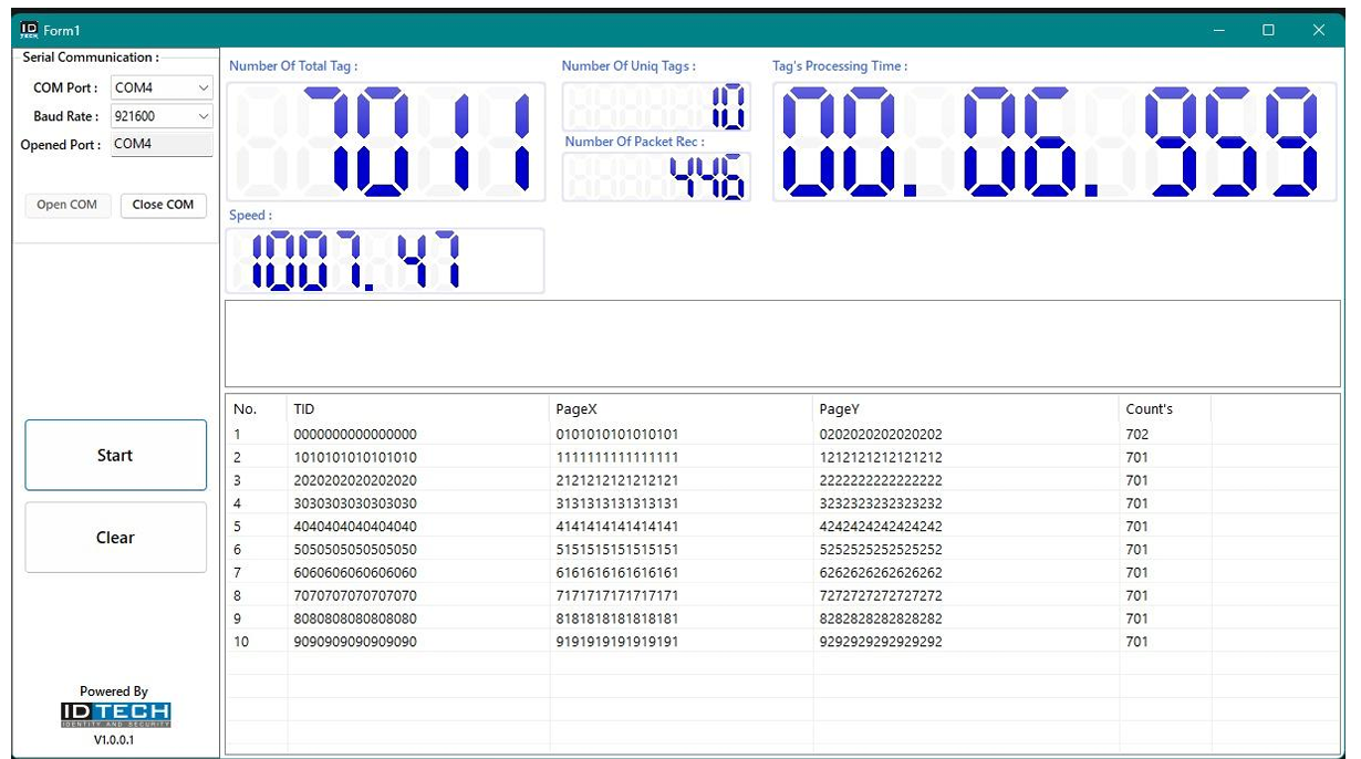
- PC Software
The ID Tech UI utility (Figure 4) is used to view statistics. Third-party COM port utilities may also be used.
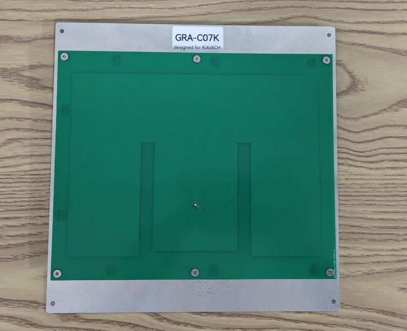
- GRA-C07K Antenna
Matched impedance and minimum VSWR at operating frequencies (Figure 5).
A loose coaxial cable may cause standing waves and hardware damage.
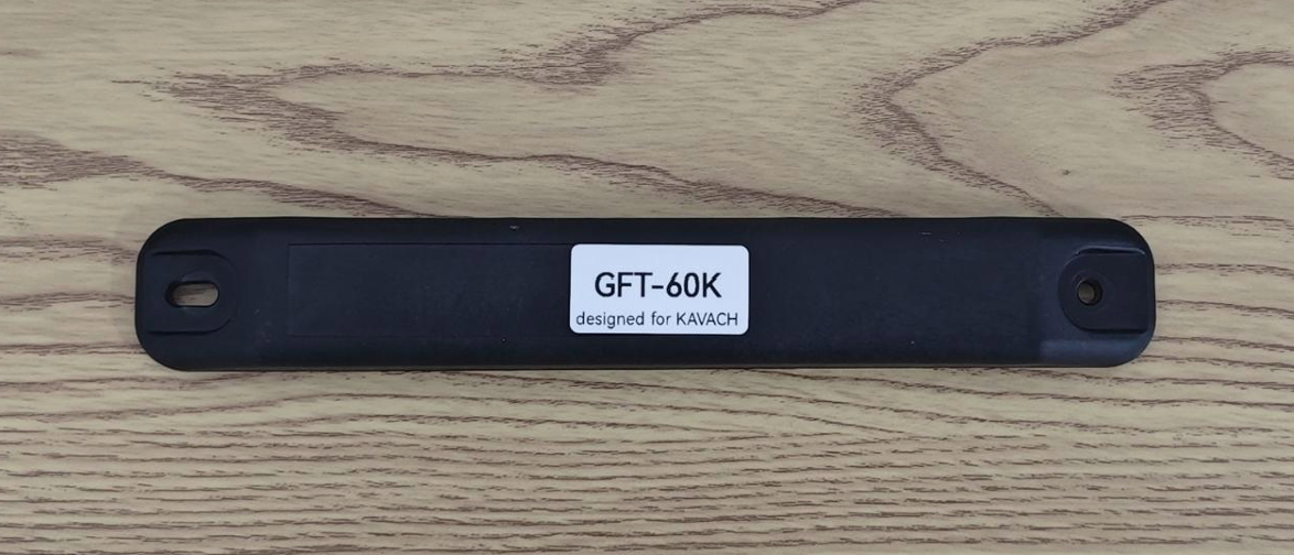
- GFT-R60K Tag
Ideal for read count tests (Figure 6). Align tag polarization with antenna.
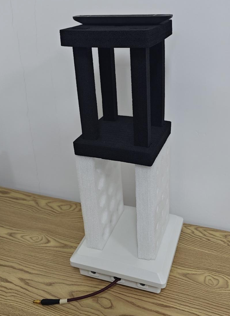
- Foam Support
Place tag on foam support 60 cm from antenna (Figure 7).
For Internal Use Only
Test Operation Guide
3. Test Procedures
3-1. DC Power Consumption
- Power the module with a DC power supply.
- Start continuous inventory.
- Calculate power consumption: Voltage × Current.
3-2. Transmit Frequency
- Connect DUT to frequency analyzer via coaxial cable.
- Start continuous inventory.
- Observe frequencies using max-hold amplitude.
Use an attenuator to prevent analyzer damage.
3-3. Transmit Power
- Connect DUT to frequency analyzer.
- Start continuous inventory.
- Measure peak amplitude for transmitted power.
Use an attenuator to prevent analyzer damage.
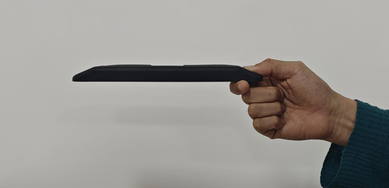
3-4. Read Range
- Start PC utility to monitor data.
- Start continuous inventory.
- Move tag while holding one end (Figure 8) to determine maximum range.
3-5. Read Count
- Start ID Tech UI utility.
- Start continuous inventory.
- Observe read count in relevant columns.
© Business Solution EBS